directive0
Human.
- 1 Post
- 10 Comments
Joined 1 year ago
Cake day: June 20th, 2023
You are not logged in. If you use a Fediverse account that is able to follow users, you can follow this user.


 2·5 months ago
deleted by creator
Wow, thats some wild hyperbole there.

GIMP really needs its Blender moment.
Blender. I feel pretty confident in saying that there is simply nothing like it in the commercial world. Its feature set is unreal; its like the swiss army knife of 3D modelling programs. I can’t say enough good things about Blender. It has replaced so many secondary programs in my workflow and is slowly dominating to become my entire workflow.
It used to suck to use in the late 2010s and then work was done to overhaul its space-shuttle cockpit interface, and now it actually feels concise and usable. I freaking love blender now. Big time blender fanboy right here.
 5·11 months ago
Hahaha, why no python?
Lotus eaters was fantastic. More of that please.
 8·1 year ago
All mac computer lab (rev a/b iMacs), locked down with foolproof. No problem; bring a zip drive and boot from it by holding down option at startup. Use resedit to edit the extension for foolproof and remove all its resources. Extension no longer works.
Reboot into a completely unrestricted finder. Good times.
 1·1 year ago
Ah yes, thanks!
Please excuse this attempt from a mere technician.
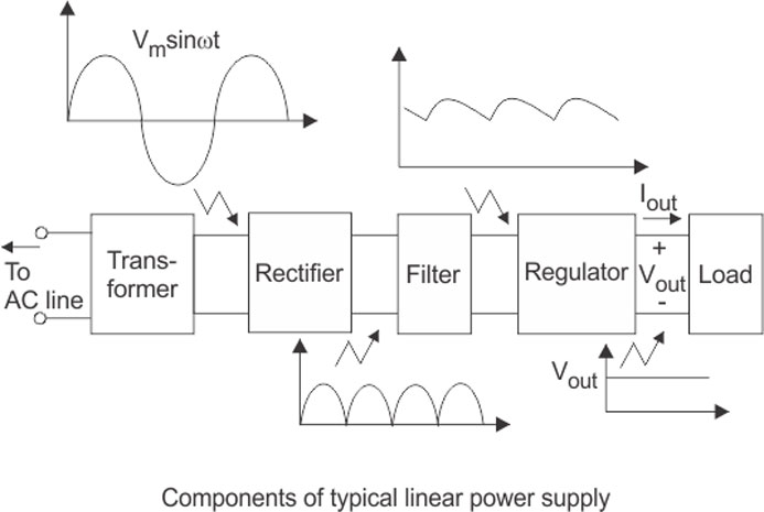
The waveform on the far left is the electrical signal fed into the rectifier. It illustrates a current that starts at zero, then reaches its full positive amplitude, then comes back to zero, then reaches the full negative, then back to zero. This represents an AC or alternating current. This is the way electricity comes out of your wall, usually.
DC or direct current is instead just a constant horizontal line. Ideally no change in the current. This is what we get from batteries and is used in most of our smaller devices like computers and smartphones. So naturally its handy to have a device that “adapts” the AC to DC. A common part of AC to DC Adapters is a rectifier.
The diagram in the center of the image is the schematic of a full bridge rectifier. It shows the two wires that feed into the rectifier on the left, these are then split into an arrangement of diodes represented by triangles with lines at their tips. Diodes essentially only allow current in one direction. The line is representative of a “direction” of the flow. The particular way these diodes are arranged means that no matter what kind of signal is fed in it will never produce a negative voltage at the output.
By using this arrangement we can feed in the AC signal and sort of flip the negative of part of that signal so the waveform looks like the one on the right. You can see that the waveform now is only above the line representing zero.
This is however only one step in the process of a power regulation and so as others have pointed out its not as simple as it may seem. Usually a transformer is used to step up or down voltages, and those are not designed to be used with DC and I believe could be damaged?
 0·1 year ago
Money.
War never changes.